
1.8インチ TFTカラーLCD 128x160 Arduino

1.8 inches 128X160 ILI9163 / ST7735 TFT LCD module with a PCB base plate SPI serial port
価格 664円 (2019/02/13現在)
- レギュレータIC付きモジュールは3.3V / 5V電源をサポート
- SDカードホルダーを使えば、デジタルフォトフレームのような実験をすることができます
- モジュールはNokia3310 / 5110インターフェースを予約し、1602インターフェースをサポートし、プラグインとプラグアウトします。
- 合理化された配線のためのIO
・LCD解像度:128×160、ドライバIC:ILI9163 / ST7735
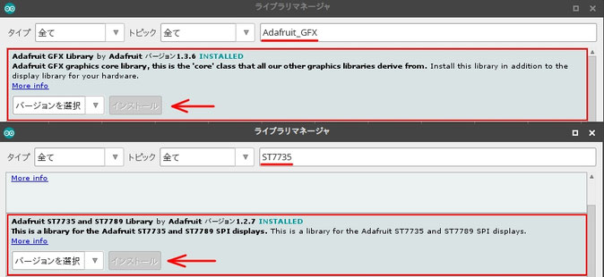
Arduino IDEにライブラリをインストール
ツールバーの 「スケッチ」 ー> 「ライブラリをインクルード」 ー> 「ライブラリを管理...」 ー> ライブラリマネージャ ダイアログが表示される。
検索をフィルタ...欄に「Adafruit_GFX」「ST7735」を入力、検索し左図の2つのライブラリをインストールする。
今回のスケッチ(プログラム)の共通部分のコード
#include <Adafruit_GFX.h> // Core graphics library
#include <Adafruit_ST7735.h> // Hardware-specific library
#include <SPI.h>
//ブレイクアウトには、2本または3本のピンを使用できます(??)
//これらのピンは1.8インチTFTシールドにも使用できます
#define TFT_RST 7 // 1-RSTピン ー> Arduino D7ピン
// これをArduinoのリセットに接続することもできます。その場合は、この#defineピンを0に設定してください。
#define TFT_CS 9 // 2-CSピン ー> Arduino D9ピン
#define TFT_DC 8 // 3-D/Cピン ー> Arduino D8ピン
// オプション1(推奨):ハードウェアSPIピンを使用し(UNOではsclk = 13とsid = 11)、ピン10は出力にする必要があります。 これははるかに高速です - あなたがmicroSDカードを使用したい場合にも必要です(画像描画の例を参照)
Adafruit_ST7735 tft = Adafruit_ST7735(TFT_CS, TFT_DC, TFT_RST);
//オプション2:任意のピンを使用しますが、少し遅くなります。
#define TFT_MOSI 11 // 4-DINピン ー> Arduino D11ピン
// Arduinoの好きなピンに設定してください。
#define TFT_SCLK 13 // 5-CLKピン ー> Arduino D13ピン
// Arduinoの好きなピンに設定してください。
//Adafruit_ST7735 tft = Adafruit_ST7735(TFT_CS, TFT_DC, TFT_MOSI, TFT_SCLK, TFT_RST);
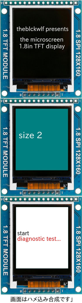
テキスト描画のコード
void setup(void) {
// 1.8" TFTの場合
tft.initR(INITR_BLACKTAB); // initialize a ST7735S chip, black tab
tft.fillScreen(ST7735_BLACK); // 画面が黒色になる。文字はクリアーされる
drawtext(5, 45, "theblckwlf presents", ST7735_WHITE); // (x=5ピクセル,y=45ピクセル,表示する文字列,文字の色) //LCD x=128,y=160 // Size(1)でFont Size(6,8)程度?
delay(4000); // 4秒休止
drawtext(15, 65, "the microscreen", ST7735_WHITE);
drawtext(10, 75, "1.8in TFT display", ST7735_WHITE);
delay(4000);
tft.fillScreen(ST7735_BLUE); // 画面が青色になる。文字はクリアーされる
tft.setTextSize(2); // 文字サイズ2
drawtext(5, 65, "size 2 ", ST7735_WHITE);
delay(4000);
tft.fillScreen(ST7735_WHITE); // 画面が白色になる。文字はクリアーされる
tft.setTextSize(1); // 文字サイズ1
drawtext(5, 65, "start ", ST7735_BLACK);
drawtext(5, 75, "diagnostic test...", ST7735_RED);
}
void loop() {}
void drawtext(int wid, int hei, char *text, uint16_t color) {
tft.setCursor(wid, hei); // カーソル位置指定
tft.setTextColor(color); // 文字の色指定
tft.setTextWrap(true); // 引数が 'true'の場合、テキスト文字列は次の行に折り返されます。
// 「false」の場合、テキストは画面から消えます。
tft.print(text); // 文字を描画
}
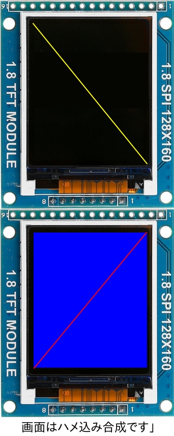
ライン描画のコード
void setup(void) {
// 1.8" TFTの場合
tft.initR(INITR_BLACKTAB); // initialize a ST7735S chip, black tab
testlines1(ST7735_YELLOW);
delay(4000);
testlines2(ST7735_RED);
delay(4000);
}
void loop() {}
void testlines1(uint16_t color) {
tft.fillScreen(ST7735_BLACK); // 画面が黒色になる。画面はクリアーされる
tft.drawLine(0, 0, 127, 159, color);
}
void testlines2(uint16_t color) {
tft.fillScreen(ST7735_BLUE); // 画面が青色になる。画面はクリアーされる
tft.drawLine(127, 0, 0, 159, color);
}
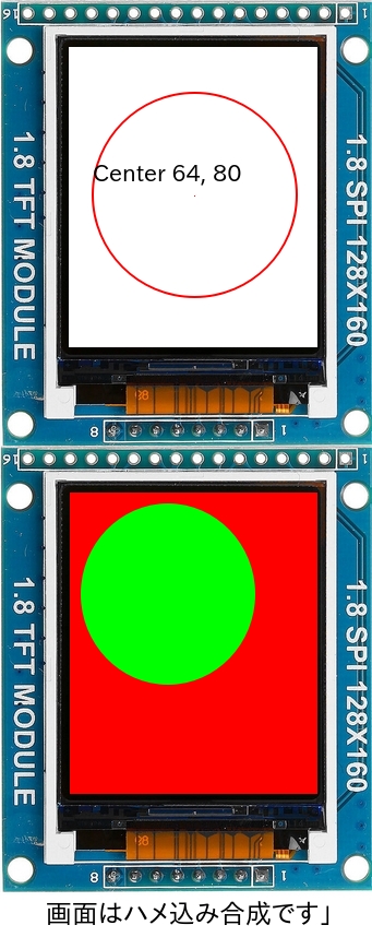
円描画のコード
void setup(void) {
// 1.8" TFTの場合
tft.initR(INITR_BLACKTAB); // initialize a ST7735S chip, black tab
tft.fillScreen(ST7735_WHITE); // 画面を白色にして、画面をクリアーする
tft.setTextSize(1); // 文字サイズ
tft.setTextColor(ST7735_BLACK); // 文字色
tft.drawPixel(tft.width()/2, tft.height()/2, ST7735_RED); // ドット表示 (x = 画面幅/2 , y = 画面高さ/2, 色)
tft.setCursor(15, (tft.height()/2)-15); // 文字の表示位置
tft.print("Center ");
tft.print(tft.width()/2);
tft.print(", ");
tft.println(tft.height()/2);
tft.drawCircle(tft.width()/2, tft.height()/2, 50, ST7735_RED); // 円描画(中心x座標, y , 半径, 色)
delay(2000);
}
void loop() {}
塗りつぶした円の描画
void setup(void) {
// 1.8" TFTの場合
tft.initR(INITR_BLACKTAB); // initialize a ST7735S chip, black tab
fillcircles(45, ST7735_GREEN);
}
void loop() {
}
void fillcircles(uint8_t radius, uint16_t color) {
tft.fillScreen(ST7735_RED);
tft.fillCircle(50, 50, radius, color);
}
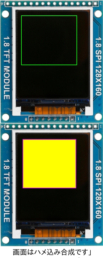
矩形の描画のコード
void setup(void) {
// 1.8" TFTの場合
tft.initR(INITR_BLACKTAB); // initialize a ST7735S chip, black tab
drawrects(ST7735_GREEN);
}
void loop() {}
void drawrects(uint16_t color) {
tft.fillScreen(ST7735_BLACK);
tft.drawRect(10, 10 , 100, 100, color);
}
塗りつぶした矩形の描画のコード
void setup(void) {
// 1.8" TFTの場合
tft.initR(INITR_BLACKTAB); // initialize a ST7735S chip, black tab
fillrects(ST7735_YELLOW, ST7735_MAGENTA);
}
void loop() {}
void fillrects(uint16_t color1, uint16_t color2) {
tft.fillScreen(ST7735_BLACK);
tft.fillRect(10, 10 , 100, 100, color1);
tft.drawRect(10, 10 , 100, 100, color2);
}
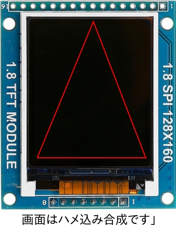
三角形の描画のコード
void setup(void) {
// 1.8" TFTの場合
tft.initR(INITR_BLACKTAB); // initialize a ST7735S chip, black tab
triangles();
}
void loop() {}
void triangles() {
tft.fillScreen(ST7735_BLACK);
int color = 0xF800;
int w = tft.width()/2;
int x = tft.height()-1;
int y = 0;
int z = tft.width();
tft.drawTriangle(w, y, y, x, z, x, color);
}
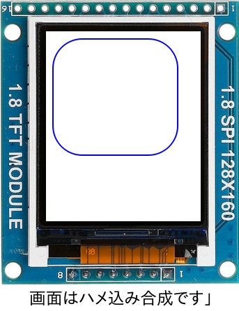
4隅がフィレットされた矩形の描画のコード
void setup(void) {
// 1.8" TFTの場合
tft.initR(INITR_BLACKTAB); // initialize a ST7735S chip, black tab
roundrects();
}
void loop() {}
void roundrects() {
tft.fillScreen(ST7735_WHITE);
int color = 155;
tft.drawRoundRect(5, 5, 100, 100, 25, color);
}
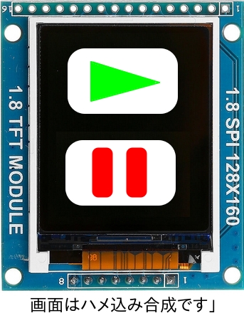
図形の組み合わせを描画のコード
void setup(void) {
// 1.8" TFTの場合
tft.initR(INITR_BLACKTAB); // initialize a ST7735S chip, black tab
mediabuttons();
}
void loop() {}
void mediabuttons() {
// play
tft.fillScreen(ST7735_BLACK);
tft.fillRoundRect(25, 10, 78, 60, 15, ST7735_WHITE);
tft.fillTriangle(42, 20, 42, 60, 90, 40, ST7735_RED);
delay(500);
// pause
tft.fillRoundRect(25, 90, 78, 60, 15, ST7735_WHITE);
tft.fillRoundRect(39, 98, 20, 45, 5, ST7735_GREEN);
tft.fillRoundRect(69, 98, 20, 45, 5, ST7735_GREEN);
delay(500);
// play color
tft.fillTriangle(42, 20, 42, 60, 90, 40, ST7735_BLUE);
delay(50);
// pause color
tft.fillRoundRect(39, 98, 20, 45, 5, ST7735_RED);
tft.fillRoundRect(69, 98, 20, 45, 5, ST7735_RED);
// play color
tft.fillTriangle(42, 20, 42, 60, 90, 40, ST7735_GREEN);
}
参考にしたサイト
Beginner Arduino - Using a 1.8 Inch TFT Display
https://www.instructables.com/id/Beginner-Arduino-Using-a-18-Inch-TFT-Display/
Adafruit GFXライブラリ資料
Arduino Adafruit GFX: Printing to the TFT Screen
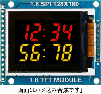
7セグ フォントを使用する
ライブラリのインストール
Arduino graphics library for ST7735 displays with propotional fonts
https://github.com/Bodmer/TFT_ST7735
スケッチ
#include <TFT_ST7735.h> // Graphics and font library for ST7735 driver chip
#include <SPI.h>
//https://github.com/Bodmer/TFT_ST7735
//のライブラリをインストールする
TFT_ST7735 tft = TFT_ST7735();
// 接続: RST --> D7, CS --> D9, D/C --> D8, DIN --> D11, CLK --> D13
void setup(void) {
tft.init();
tft.setRotation(1); //90度回転表示
tft.fillScreen(ST7735_BLACK); //画面をクリアーして黒色にする
tft.setTextColor(ST7735_RED, ST7735_BLACK); // 文字色
// 7セグメント表示
// キャラクタの種類 [space] 0 1 2 3 4 5 6 7 8 9 0 : .
tft.drawString("12:34",5,5,7); // (characters,x座標,y座標,7)
tft.setTextColor(ST7735_YELLOW, ST7735_BLACK);
tft.drawString("56:78",5,69,7);
delay(1000);
tft.fillScreen(ST7735_WHITE); //画面をクリアーして白色にする
tft.setTextColor(TFT_BLUE);
tft.setCursor (20, 52);
tft.setTextSize(5);
tft.print("text");
}
void loop() {}
参考にしたサイト
Adjusting Dual Clock using DS3231 on 1.8" ST7735 Display
https://www.hackster.io/user0035382/adjusting-dual-clock-using-ds3231-on-1-8-st7735-display-3ba172