
Arduino 7 Segment LED Display and Counter – Tutorial
ネタ元
http://www.electroschematics.com/9636/arduino-segment-display-counter/
スイッチを押すたびにカウントアップし、0〜9を7セグLEDに表示する。
//Arduino
/*
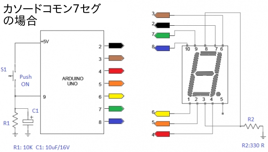
Arduino 7-Segment LED Display for Common Cathode Displays
Arduino Pins: 2,3,4,5,6,7,8
Display Pins: 7,6,4,2,1,9,10
Display Pins 3&8 should go to GND
Switch Input is at Pin 9
Source: http://www.electroschematics.com/9636/arduino-segment-display-counter/
*/
// 0 , 1 ,
2 , 3 , 4
,
// 5 , 6 ,
7 , 8 , 9
byte numbers[10] = {
B11111100, B01100000, B11011010, B11110010, B01100110,
B10110110, B10111110, B11100000, B11111110, B11100110
};
void setup() {
for(int i = 2; i <= 8; i++) {
pinMode(i, OUTPUT);
}
pinMode(9, INPUT);
}
int counter = 0;
bool go_by_switch = true;
int last_input_value = LOW;
void loop() {
if(go_by_switch) {
int switch_input_value = digitalRead(9);
if(last_input_value == LOW && switch_input_value == HIGH) {
counter = (counter + 1) % 10;
}
last_input_value = switch_input_value;
} else {
delay(500);
counter = (counter + 1) % 10;
}
writeNumber(counter);
}
void writeNumber(int number) {
if(number < 0 || number > 9) {
return;
}
byte mask = numbers[number];
byte currentPinMask = B10000000;
for(int i = 2; i <= 8; i++) {
// if(mask & currentPinMask) digitalWrite(i,HIGH); //カソードコモンタイプ7セグメント
// else
digitalWrite(i,LOW); //カソードコモンタイプ7セグメント
if(mask & currentPinMask) digitalWrite(i,LOW); //アノードコモンタイプ7セグメント
else
digitalWrite(i,HIGH); //アノードコモンタイプ7セグメント
currentPinMask = currentPinMask >> 1;
}
}
//mbed L476RG
/*
L476RG Pins: D2,D3,D4,D5,D6,D7,D8
Display Pins: 7,6,4,2,1,9,10
Display Pins 3&8 should go to GND
Switch Input is at Pin D9
*/
// 0 , 1 , 2
, 3 , 4
,
// 5 , 6 , 7
, 8 , 9
int numbers[10] = {
0B11111100, 0B01100000, 0B11011010,
0B11110010, 0B01100110,
0B10110110, 0B10111110, 0B11100000, 0B11111110,
0B11100110
};
DigitalOut seven_seg_1(D6);
DigitalOut seven_seg_2(D5);
DigitalOut seven_seg_4(D4);
DigitalOut seven_seg_6(D3);
DigitalOut seven_seg_7(D2);
DigitalOut seven_seg_9(D7);
DigitalOut seven_seg_10(D8);
DigitalIn Count(D9);
int counter = 0;
bool go_by_switch = true;
int last_input_value = 0;
int main() {
while(1) {
if(go_by_switch) {
int switch_input_value = Count;
if(last_input_value == 0 && switch_input_value == 1) {
counter = (counter + 1) % 10;
}
last_input_value = switch_input_value;
} else {
wait(0.5); // 0.5 sec
counter = (counter + 1) % 10;
}
writeNumber(counter);
}
}
void writeNumber(int number) {
if(number < 0 || number > 9) {
return;
}
int mask = numbers[number];
int currentPinMask = 0B10000000;
int segm[9];
for(int i = 2; i <= 8; i++) {
// if(mask & currentPinMask) segm[i] = 1; //カソードコモンタイプ7セグメント
// else segm[i] =
0; //カソードコモンタイプ7セグメント
if(mask & currentPinMask) segm[i] = 0; //アノードコモンタイプ7セグメント
else segm[i] =
1;
//アノードコモンタイプ7セグメント
currentPinMask = currentPinMask >> 1;
}
seven_seg_2 = segm[2];
seven_seg_3 = segm[3];
seven_seg_4 = segm[4];
seven_seg_5 = segm[5];
seven_seg_6 = segm[6];
seven_seg_7 = segm[7];
seven_seg_8 = segm[8];
}
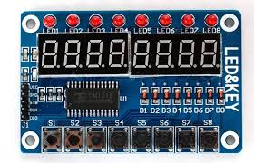
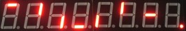
8x LED Display + Keys + LEDs Module - TM1638
Amazonで購入
HiLetgo 8ビット LED デジタル チューブ 8キー TM1638 ディスプレイ モジュール for AVR Arduino ARM
https://www.amazon.co.jp/HiLetgo-TM1638-%E3%83%87%E3%82%A3%E3%82%B9%E3%83%97%E3%83%AC%E3%82%A4-%E3%83%A2%E3%82%B8%E3%83%A5%E3%83%BC%E3%83%AB-Arduino/dp/B01D140BT6?ie=UTF8&ref_=pe_492632_233155642_TE_item価格: ¥ 350 & 関東への配送料無料 (2016.06.15現在-価格は常に変動しています。少し前は300円でした)届くまで1〜3週間かかります。
参考にしたHP
http://www.sunrom.com/p/8x-led-display-keys-leds-module-tm1638
スケッチの参考HP
https://blog.3d-logic.com/2015/01/10/using-a-tm1638-based-board-with-arduino/
Arduino   と   TM1638 based board の接続          TM1638 based board と  L476RG  の接続
3.3V   ----------- VCC                                         VCC  -----------------  3.3V
GND    ----------- GND                                         GND  -----------------  GND
PIN #7 ----------- STB                                         STB  -----------------  D7 (CS)
PIN #9 ----------- CLK                                         CLK  -----------------  D13 (SCK)
PIN #8 ----------- DIO                                         DIO  --------┬-------  D12 (MISO)
                                                               (DIN,DOUT)   └-1kΩ--  D11 (MOSI)
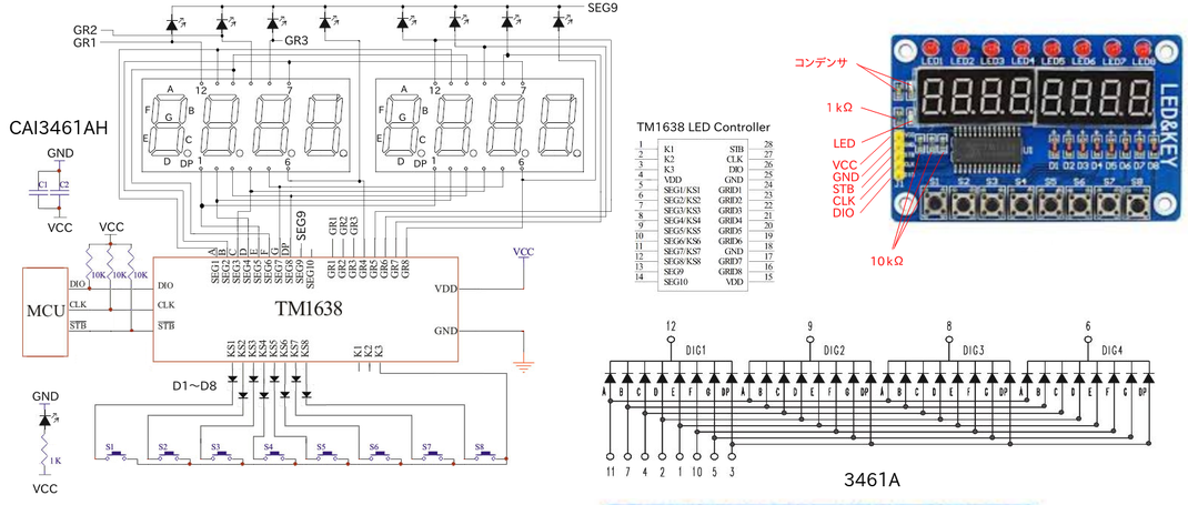
上図の回路は、基板のパターンが見えないのでテスターで導通テストだけで作成したので、間違っている可能性もあります。
//Arduino用
//サンプル スケッチ
const int strobe = 7;
const int clock = 9;
const int data = 8;
void sendCommand(uint8_t value)
{
digitalWrite(strobe, LOW);
shiftOut(data, clock, LSBFIRST, value);
digitalWrite(strobe, HIGH);
}
void reset()
{
sendCommand(0x40); // set auto increment mode
digitalWrite(strobe, LOW);
shiftOut(data, clock, LSBFIRST, 0xc0); // set starting address to 0
for(uint8_t i = 0; i < 16; i++)
{
shiftOut(data, clock, LSBFIRST, 0x00);
}
digitalWrite(strobe, HIGH);
}
void setup()
{
pinMode(strobe, OUTPUT);
pinMode(clock, OUTPUT);
pinMode(data, OUTPUT);
sendCommand(0x8f); // activate
reset();
}
#define COUNTING_MODE 0
#define SCROLL_MODE 1
#define BUTTON_MODE 2
void loop()
{
static uint8_t mode = COUNTING_MODE;
switch(mode)
{
case COUNTING_MODE:
mode += counting();
break;
case SCROLL_MODE:
mode += scroll();
break;
case BUTTON_MODE:
buttons();
break;
}
delay(200);
}
bool counting()
{
/*0*/ /*1*/ /*2*/ /*3*/ /*4*/ /*5*/ /*6*/ /*7*/ /*8*/
/*9*/
uint8_t digits[] = { 0x3f, 0x06, 0x5b, 0x4f, 0x66, 0x6d, 0x7d, 0x07, 0x7f, 0x6f };
static uint8_t digit = 0;
sendCommand(0x40);
digitalWrite(strobe, LOW);
shiftOut(data, clock, LSBFIRST, 0xc0);
for(uint8_t position = 0; position < 8; position++)
{
shiftOut(data, clock, LSBFIRST, digits[digit]);
shiftOut(data, clock, LSBFIRST, 0x00);
}
digitalWrite(strobe, HIGH);
digit = ++digit % 10;
return digit == 0;
}
bool scroll()
{
uint8_t scrollText[] =
{
/* */ /* */ /* */ /* */ /* */ /* */ /* */ /* */
0x00, 0x00, 0x00, 0x00, 0x00, 0x00, 0x00, 0x00,
/*H*/ /*E*/ /*L*/ /*L*/ /*O*/ /*.*/ /*.*/ /*.*/
0x76, 0x79, 0x38, 0x38, 0x3f, 0x80, 0x80, 0x80,
/* */ /* */ /* */ /* */ /* */ /* */ /* */ /* */
0x00, 0x00, 0x00, 0x00, 0x00, 0x00, 0x00, 0x00,
/*H*/ /*E*/ /*L*/ /*L*/ /*O*/ /*.*/ /*.*/ /*.*/
0x76, 0x79, 0x38, 0x38, 0x3f, 0x80, 0x80, 0x80,
};
static uint8_t index = 0;
uint8_t scrollLength = sizeof(scrollText);
sendCommand(0x40);
digitalWrite(strobe, LOW);
shiftOut(data, clock, LSBFIRST, 0xc0);
for(int i = 0; i < 8; i++)
{
uint8_t c = scrollText[(index + i) % scrollLength];
shiftOut(data, clock, LSBFIRST, c);
shiftOut(data, clock, LSBFIRST, c != 0 ? 1 : 0);
}
digitalWrite(strobe, HIGH);
index = ++index % (scrollLength << 1);
return index == 0;
}
void buttons()
{
uint8_t promptText[] =
{
/*P*/ /*r*/ /*E*/ /*S*/ /*S*/ /* */ /* */ /* */
0x73, 0x50, 0x79, 0x6d, 0x6d, 0x00, 0x00, 0x00,
/* */ /* */ /* */ /* */ /* */ /* */ /* */ /* */
0x00, 0x00, 0x00, 0x00, 0x00, 0x00, 0x00, 0x00,
/*b*/ /*u*/ /*t*/ /*t*/ /*o*/ /*n*/ /*S*/ /* */
0x7c, 0x1c, 0x78, 0x78, 0x5c, 0x54, 0x6d, 0x00,
/* */ /* */ /* */ /* */ /* */ /* */ /* */ /* */
0x00, 0x00, 0x00, 0x00, 0x00, 0x00, 0x00, 0x00,
};
static uint8_t block = 0;
uint8_t textStartPos = (block / 4) << 3;
for(uint8_t position = 0; position < 8; position++)
{
sendCommand(0x44);
digitalWrite(strobe, LOW);
shiftOut(data, clock, LSBFIRST, 0xC0 + (position << 1));
shiftOut(data, clock, LSBFIRST, promptText[textStartPos + position]);
digitalWrite(strobe, HIGH);
}
block = (block + 1) % 16;
uint8_t buttons = readButtons();
for(uint8_t position = 0; position < 8; position++)
{
uint8_t mask = 0x1 << position;
setLed(buttons & mask ? 1 : 0, position);
}
}
uint8_t readButtons(void)
{
uint8_t buttons = 0;
digitalWrite(strobe, LOW);
shiftOut(data, clock, LSBFIRST, 0x42);
pinMode(data, INPUT);
for (uint8_t i = 0; i < 4; i++)
{
uint8_t v = shiftIn(data, clock, LSBFIRST) << i;
buttons |= v;
}
pinMode(data, OUTPUT);
digitalWrite(strobe, HIGH);
return buttons;
}
void setLed(uint8_t value, uint8_t position)
{
pinMode(data, OUTPUT);
sendCommand(0x44);
digitalWrite(strobe, LOW);
shiftOut(data, clock, LSBFIRST, 0xC1 + (position << 1));
shiftOut(data, clock, LSBFIRST, value);
digitalWrite(strobe, HIGH);
}
ライブラリを使って使用する
TM1638 Library
https://github.com/rjbatista/tm1638-library
#include <TM1638.h>
//TM1638 module(DIO, CLK, STB);
TM1638 module(8, 9, 7);
void setup()
{
module.setDisplayToDecNumber(12345678,0,false); //数値
delay(3000); //表示 12345678
module.setDisplayToDecNumber(12345678,1,false); //0は小数点なし、1は最後に小数点、2は最後から2番目に小数点、・・・、128は小数点最後から8番目に小数点を点灯する。 3の場合最後と2番目が点灯する。
//例(12345678,8,false);の場合は、 12345.678と表示される
delay(3000); //表示 12345678.
module.setDisplayToDecNumber(1234.5678,1,true); //trueは前を0で埋める
delay(3000); //表示 00001234. //小数点以下は表示されない
module.setDisplayToDecNumber(1234.5678,1,false); //falseは前を0で埋めない
delay(3000); //表示 1234. //小数点以下は表示されない
module.setDisplayToHexNumber(0x9abcdef0,0,false); //16進数値
delay(3000); //表示 9AbCdEF0
module.setDisplayToBinNumber(0b00001010,0); //2進数値
delay(3000); //表示 00001010
//7SEGでは文字が特殊で読めない or 見にくい
module.setDisplayToString("abcdefgh");
delay(5000); //表示 abcde「9h
module.setDisplayToString("ijklmnop");
delay(5000); //表示: 特殊フォントのため表示不可
module.setDisplayToString("qrstuvwx");
delay(5000); //表示: 特殊フォントのため表示不可
module.clearDisplay();
module.setDisplayToString("yz");
delay(3000); //表示: y2
module.setDisplayToString("ABCDEFGH");
delay(5000); //表示 A8C0EFGH
module.setDisplayToString("IJKLMNOP");
delay(5000);
module.setDisplayToString("QRSTUVWX");
delay(5000);
module.clearDisplay();
module.setDisplayToString("YZ");
delay(3000);
module.setDisplayToString("12.30");
delay(5000); //表示 12.30
module.setDisplayToString("01." "30" "30");
delay(5000); //表示 01.3030
module.clearDisplay();
}
void loop()
{
}
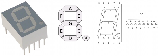
7セグのフォントを作成する
点灯セグメント 数値
A 1
B 2
C 4
D 8
E 16
F 32
G 64
DP 128
スケッチ
#include <TM1638.h>
// define a module on data pin 8, clock pin 9 and strobe pin 7
TM1638 module(8, 9, 7);
byte values[] = { 1, 2, 4, 8, 16, 32, 64, 128 };
//セグメント表示 A, B, C, D, E, F, G, DP
void setup(){
module.setDisplay(values);
}
void loop(){}
#include <TM1638.h>
// define a module on data pin 8, clock pin 9 and strobe pin 7
TM1638 module(8, 9, 7);
byte values[] = { 121, 73, 79, 33, 12, 57, 9, 15 };
//セグメント表示 A, B, C, D, E, F, G, DP
void setup(){
module.setDisplay(values);
}
void loop(){}


A I Q Y
B J R Z
C K S a
D L T b
E M U c
F N V d
G O W e
H P X
TM1638 FONT(Arduino用)
暗号見たいだ!
//mbed NUCLEO-L476RG
https://developer.mbed.org/components/TM1638-LED-controller-80-LEDs-max-Keyboa/ライブラリ
上記URLの
Hello World
mbed_TM1638のimport programボタンを押すとテストプログラムがインポートされる。
以下を変更する。
main.cpp
98 //TM1638_LEDKEY8 declaration
99 //TM1638_LEDKEY8 LEDKEY8(p5,p6,p7, p8); //LPC1768用
100 TM1638_LEDKEY8 LEDKEY8(D11,D12,D13, D7); //L476RG用
//LPC1114 + mbeduino shield用
#include "mbed.h"
#include "TM1638.h"
#include "shield.h" //LPC1114FDH28/102のマイコンキットの製作の記事にあり
//TM1638_LEDKEY8 declaration
// (MOSI,MISO,SCK,CS)
TM1638_LEDKEY8 LEDKEY8(D11,D12,D13,D7); //LPC1114用(#include "shield.h"が必要)
int main() {
long a = 12345678;
LEDKEY8.cls();
LEDKEY8.locate(0);
LEDKEY8.printf("%ld",a); //10進で出力 表示:12345678
wait(2.0);
LEDKEY8.cls();
LEDKEY8.locate(0);
LEDKEY8.printf("%lx",a); //16進で出力 表示:bC614E
wait(5.0);
LEDKEY8.cls();
LEDKEY8.locate(0);
LEDKEY8.printf("%lo",a); //8進で出力 表示:57060516
wait(5.0);
LEDKEY8.cls();
LEDKEY8.printf("abcdefgh"); //表示: AbCdEFGH
wait(20.0);
LEDKEY8.cls();
LEDKEY8.printf("ijklmnop"); //表示: 特殊フォントのため表示不可
wait(20.0);
LEDKEY8.cls();
LEDKEY8.printf("qrstuvwx"); //表示: 特殊フォントのため表示不可
wait(20.0);
LEDKEY8.cls();
LEDKEY8.printf("yz"); //表示: y2
}
マトリックススイッチ 16キーキーボード
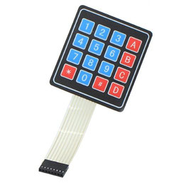
4x4 マトリックススイッチ 16キー キーボード
https://www.amazon.co.jp/dp/B00YQZEDU8/ref=pe_492632_233519652_TE_3p_dp_1
価格: ¥ 164 & 関東への配送料無料(価格は変動します)
参考URL
http://playground.arduino.cc/Code/Keypad#Download
Keypad Library for Arduino
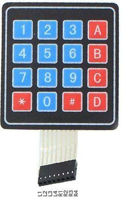
接続
4x4 keypad - Arduino
L1 9
L2 8
L3 7
L4 6
R1 5
R2 4
R3 3
R4 2
//Arduino
#include <Keypad.h>
const byte ROWS = 4; //four rows
const byte COLS = 4; //four columns
//define the cymbols on the buttons of the keypads
char hexaKeys[ROWS][COLS] = {
{'1','2','3','A'},
{'4','5','6','B'},
{'7','8','9','C'},
{'*','0','#','D'}
};
//connect to the row pinouts of the keypad 行
byte rowPins[ROWS] = {9, 8, 7, 6};
// L1,L2,L3,L4
//connect to the column pinouts of the keypad 桁
byte colPins[COLS] = {5, 4, 3, 2};
// R1,R2,R3,R4
//initialize an instance of class NewKeypad
Keypad customKeypad = Keypad( makeKeymap(hexaKeys), rowPins, colPins, ROWS, COLS);
void setup(){
Serial.begin(9600);
}
void loop(){
char customKey = customKeypad.getKey();
if (customKey){
Serial.println(customKey);
}
}
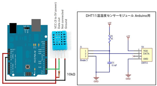
DHT11温湿度センサーモジュール
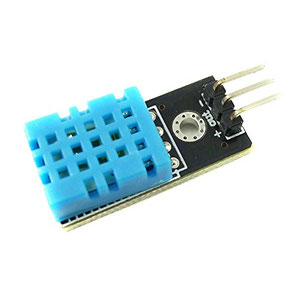
DHT11温湿度センサーモジュール Arduino用
https://www.amazon.co.jp/dp/B010PZZPLS/ref=pe_492632_233519652_TE_3p_dp_1
価格: ¥ 198 & 関東への配送料無料 (価格は変動します)
動作電圧:DC 5V
湿度測定範囲: 20-90% RH
湿度精度: ± 5% RH
温度測定範囲:0〜60℃
温度測定精度:±2℃
参考URL
https://learn.adafruit.com/dht?view=all
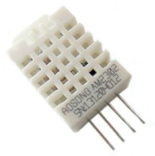
Details about DHT22/AM2302 Digital Temperature And Humidity Sensor
http://www.ebay.com/itm/381605063274?_trksid=p2060353.m2749.l2649&ssPageName=STRK%3AMEBIDX%3AIT
296円(送料無料)中国発送のため届くまでに2〜3週間程度かかります。
DHT11があまりにも精度が悪そうなので、DHT22を購入し比べました。(電圧 5V)
Arduinoの同じスケッチでDHTTYPEのみ DHT11 or DHT22 を変更。
型番 気温(℃) 湿度(%)
DHT11 33 39
DHT 22 35.6 45
温度計 36 (アルコール式)
DHT11は温度、湿度センサーとしては使い物になりませんね。(暑い〜)
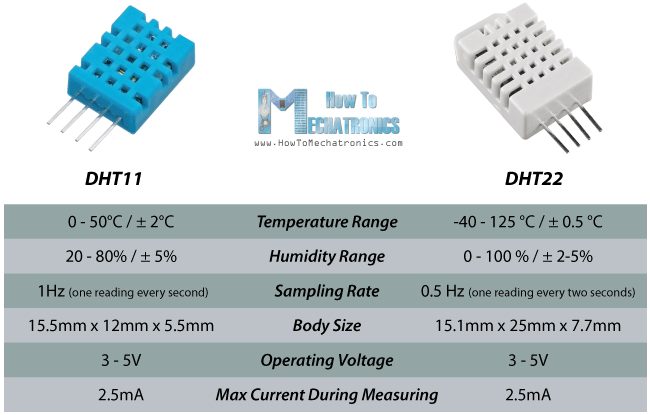
温度の精度が±2℃の為か3℃単位で上がったり下がったりすることが多い。
実用的に使用するならDHT22(±0.5℃)を使用するほうが良い。
湿度精度は±2〜5%
Vcc電圧を3.3Vに変更すると温度表示は変わらなかったが、湿度は5Vの時に42%表示だったのが3.3Vだと40%と2%下がった。
//Arduino
// adafruit_DHT-sensor_library付属のサンプルスケッチ
#include "DHT.h"
#define DHTPIN 2 // what digital pin we're connected to
#define DHTTYPE DHT11 // DHT 11
DHT dht(DHTPIN, DHTTYPE);
void setup() {
Serial.begin(9600);
dht.begin();
}
void loop() {
delay(2000);
float h = dht.readHumidity();
// Read temperature as Celsius (the default)
float t = dht.readTemperature();
// Read temperature as Fahrenheit (isFahrenheit = true)
float f = dht.readTemperature(true);
// Check if any reads failed and exit early (to try again).
if (isnan(h) || isnan(t) || isnan(f)) {
Serial.println("Failed to read from DHT sensor!");
return;
}
// Compute heat index in Fahrenheit (the default)
float hif = dht.computeHeatIndex(f, h);
// Compute heat index in Celsius (isFahreheit = false)
float hic = dht.computeHeatIndex(t, h, false);
Serial.print("Humidity: ");
Serial.print(h);
Serial.print(" %\t");
Serial.print("Temperature: ");
Serial.print(t);
Serial.print(" *C ");
Serial.print(f);
Serial.print(" *F\t");
Serial.print("Heat index: ");
Serial.print(hic);
Serial.print(" *C ");
Serial.print(hif);
Serial.println(" *F");
}
DHT11,DHT22 Library
https://developer.mbed.org/cookbook/Grove-temperature--humidity-sensors
//LPC1114 + mbeduino shield用
#include "mbed.h"
#include "DHT.h"
#include "shield.h" //LPC1114FDH28/102のマイコンキットの製作の記事にあり
Serial pc(SERIAL_TX, SERIAL_RX); //shield.hに定義
DigitalOut myled(LED1);
//DHT sensor(p23,SEN11301P); // Use the SEN11301P sensor
DHT sensor(D2,SEN11301P); // Use the SEN11301P sensor
int main() {
int err;
pc.printf("\r\nDHT Test program");
pc.printf("\r\n******************\r\n");
wait(1); // wait 1 second for device stable status
while (1) {
myled = 1;
err = sensor.readData();
if (err == 0) {
pc.printf("Temperature is %4.2f C \r\n",sensor.ReadTemperature(CELCIUS));
pc.printf("Temperature is %4.2f F \r\n",sensor.ReadTemperature(FARENHEIT));
pc.printf("Temperature is %4.2f K \r\n",sensor.ReadTemperature(KELVIN));
pc.printf("Humidity is %4.2f \r\n",sensor.ReadHumidity());
pc.printf("Dew point is %4.2f \r\n",sensor.CalcdewPoint(sensor.ReadTemperature(CELCIUS), sensor.ReadHumidity()));
pc.printf("Dew point (fast) is %4.2f \r\n",sensor.CalcdewPointFast(sensor.ReadTemperature(CELCIUS),
sensor.ReadHumidity()));
} else
pc.printf("\r\nErr %i \n",err);
myled = 0;
wait(5);
}
}
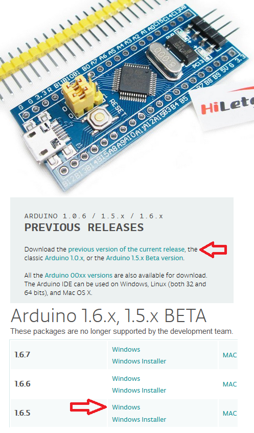
STM32F103C8T6搭載のボードをAmazonで購入
HiLetgo STM32F103C8T6 ARM STM32 Minimum システム 開発ボードモジュール Arduinoと互換
価格: ¥ 420 & 関東への配送料無料 (2016.6現在。価格は変動します)
ネットで検索するとArduino IDEが使えるらしい。
2016.1現在で使用できるArduino IDEは1.6.4と1.6.5です。
Ubuntuは1.6.9がインストールされていたので、Windows10を使用します。
2016.6.17ダウンロードしたものは1.6.9が使用できると書いてました。
Windows用1.6.5をダウンロードして適当な所に展開する。
https://www.arduino.cc/en/Main/Software
Arduino for STM32をインストール
参考URL
https://github.com/rogerclarkmelbourne/Arduino_STM32/wiki
英語のサイトですからブラウザの翻訳機能で翻訳が必要(私はFirefoxのアドオンでGoogle翻訳を使用)
installation ➡
All OS's
•Download zip file containing the STM32 files from here
「here」がダウンロードのリンク
Arduino_STM32-master.zip がダウンロードされるので、Arduino IDEのフォルダの下にhardwareというフォルダがあるので、この中に展開する。
Arduino IDEを起動して
ツール ➡ ボード でSTM32Boardsが選択できる。
Windows10もUbuntuもスケッチをコンパイルの段階でファイルがない?エラーでコンパイル不可?
どうもgcc-arm-none-eabiがインストールされていないらしい。
gcc-arm-none-eabiなんて何処にも書いていなかった気がするが、
Ubuntの場合
sudo apt install gcc-arm-none-eabi
でインストールする。
インストールしても同じエラーが出る。
インストールされているフォルダが違うみたい。
ArduinoIDEで{runtime.tools.arm-none-eabi-gcc.path}/bin/arm-none-eabi-g++: no such file or directoryとエラーがでているが、{runtime.tools.arm-none-eabi-gcc.path}が何処かわからない?
/hardware/tools/arm/bin/等にシンボリックリンクを貼っても駄目だ。
ググっても同じエラーで困っている人がいるが解決出来ない。
{runtime.tools.arm-none-eabi-gcc.path}このパスが何処で定義されているのかな?
これを解決すればいけそうだ。
Windows10 64bitの場合
64bit用が無く32bit用をインストールしたが駄目だった。
Windows7 32bit/64bitをサポートしているみたい。
こりゃ駄目だ、Ubuntuで頑張るか。
Arduino_STM32はエラーでコンパイル出来ない状態ですが,mbedで成功しました。
NUCLEOボードを使ってmbedで開発することができました。
(LPC1114FN28用のmbedインターフェースはMCU毎にファームウエアが異なるため、そのMUC専用のファームウエアをその都度書き込む必要があるらしい)
Platforms はNUCLEO-F103RBを選択する。
NUCLEO L476RGはmbedフォルダにコンパイルした*.binファイルをコピーするとすぐに実行しましたが、STM32F103C8T6はコピーした後リセットボタンを押したあと実行されます。
LPC1114FDH28/102のマイコンキットの製作
aitenndo
DIP化最小構成マイコンキット [K-FDH28]
http://www.aitendo.com/product/12257
販売価格: 395円(税別)
LPC1114FN28のDIP28Pinの大きさの中に必要最小限の部品が入ります。
最初はDIP28Pinのチップで自作しようと思ったが秋月電子通商のLPC1114FN28の値段が180円から400円に値上がりしていた。
●構成部品一覧
表面実装1206サイズ抵抗(R1):330Ω(x1)
表面実装1206サイズコンデンサ(C3、C4):104(x2)
表面実装1206サイズコンデンサ(C1、C2):15〜22pF(x2)
3mm LED:赤(x1)
タクトスイッチ:3x6(x1)
クリスタル(HC49S):12.000MHz(x1)
2.54mmピッチ単列ピンヘッダ:40P(x1)
2.54mmピッチ2Pジャンパー(x1)
チップIC :LPC1114FDH28(x1)
基板:(x1)
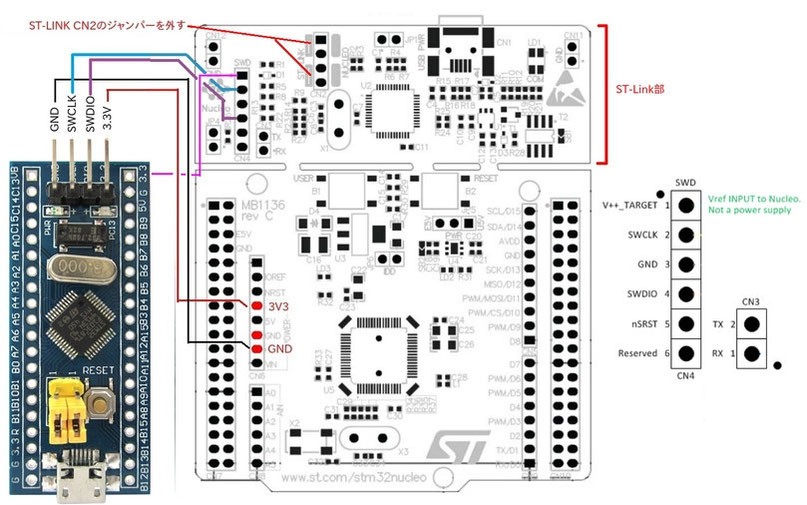
次にプログラムを書き込むためにNucleo STM32L476RGのST-Linkをつないだらエラーメッセージのファイルができている??
STMのMCUしか使えないみたい。
ググッていたら、トラ技ARMライタの記事に同じメーカのMCUでもMCUが違うとファームウエアもそのMCU専用のが必要らしい。
現在トラ技ARMライタのファームウエアがLPC1114とLPC11U35用の2種類あるらしい。
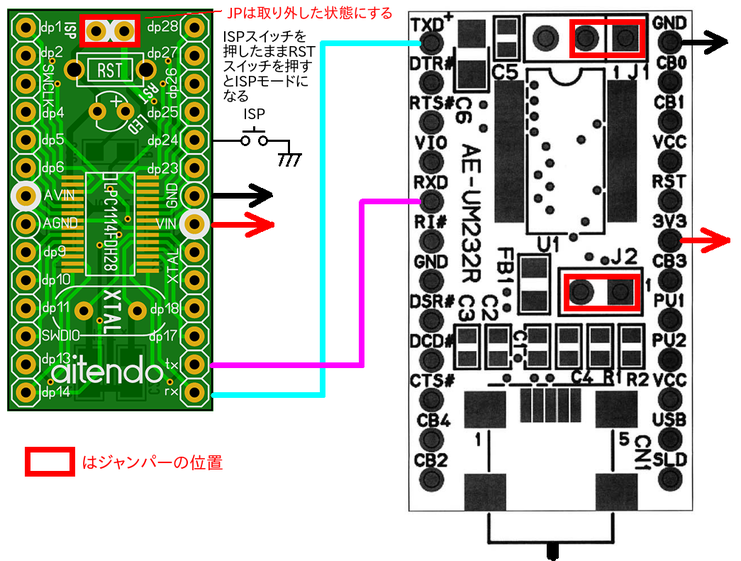
とりあえず動作確認するためにUSBシリアル 秋月電子のAE-UM232Rで書き込みました。
FT232RLのドライバーはインストールしていません。Ubuntuではそのまま使えるみたい。
ISPで書き込むソフトウェアはlpc21ispを使いました。
使い方はhttps://developer.mbed.org/users/ytsuboi/notebook/getting-started-with-mbed-lpc1114-ja/
を参照。
インストールも簡単でした。うまくインストールできるか心配でしたがあっさりと終了。
Readmeにmake -f Makefile.gnu clean allって書いてあったが、Makefile.gnuがないって怒られた。
make -f Makefile clean all
でインストール終了(OSはUbuntu Studio)
これはインストールというよりもビルドしただけ。端末から起動するときに、Pathとコマンド名が必要。
apt-getでもインストールできると後でわかった。
sudo apt install lpc21isp
そして実行。コマンドラインからシコシコ打ち込むのがめんどくさい〜。実際はコピペやけどやっぱりメンドイ。やっぱりmbedインタフェースが必要。
$ ./lpc21isp -bin ./program_bin_files/ファイル名.bin /dev/ttyUSB0 115200 48000
(Windows用のISP書込み 補助ツールというのがありました。これは、lpc21ispをgui化したものです。
https://developer.mbed.org/users/okini3939/notebook/flash-program/)
Ubuntu用にシェルスプリクトを作って少しでもキー入力を少なくする。
使い方
$ ./lpc21isp.sh ファイル名.bin
lpc21isp.sh
-------------------------------
#!/bin/bash
echo "mbedでコンパイルした*.binファイルは/media/・・・/ISP/lpc21isp_197/program_bin_files/に保存します。"
echo "実行方法は ./lpc21isp_sh ファイル名.bin"
./lpc21isp -bin ./program_bin_files/$1 /dev/ttyUSB0 115200 48000
echo "Synchronizing (ESC to abort)........................."
echo ".................................... no answer on '?'"
echo "と表示されたら失敗です。USBケ-ブルを一度抜いて、少し時間をおいて再び差し込んで再度実行してください。"
-------------------------------
chmod +x lpc21isp.sh -->実行権限を与える
ls -l lpc21isp.sh
-rwxrwxrwx 1 xx xx 564 7月 10 12:09 lpc21isp.sh
program_bin_filesフォルダにmbedでコンパイルしてからダウンロードします。
/dev/ttyUSB0は環境によって異なります。私のUbuntu環境だとArduino互換機、AE-UM232Rが/dev/ttyUSB0でNucleo STM32L476RGだと/dev/ttyACM0でした。
ISPのJPを外した状態で、dp24にタクトスイッチ(ISP)を取り付けて片側をGNDに接続する。
プログラムを書き込む前にISPスイッチを押した状態でリセットボタンを押す。
これで書き込むとUSBケーブルを外さなくても次の書き込みができる。
<あれれ??USBケーブル接続したまま、次の書き込みやったら接続に失敗する。>
<USBケーブルを抜いて1分くらいしてからUSBケーブルをPCに接続する。>
成功時
$ ./lpc21isp -bin ./program_bin_files/mbed_blinky_LPC1114FN28_LPC1114.bin /dev/ttyUSB0 115200 48000
lpc21isp version 1.97
File ./program_bin_files/mbed_blinky_LPC1114FN28_LPC1114.bin:
loaded...
image size : 10376
Image size : 10376
Synchronizing (ESC to abort). OK
Read bootcode version: 1
7
Read part ID: LPC1114.../102, 32 kiB FLASH / 4 kiB SRAM (0x1A40902B)
Will start programming at Sector 1 if possible, and conclude with Sector 0 to ensure that checksum is written last.
Erasing sector 0 first, to invalidate checksum. OK
Sector 1: ...........................|.........................|.........................|.........................
Sector 2: ...........................|.........................|.....
Sector 0: ..........................|.........................|.........................|.........................
Download Finished... taking 2 seconds
Now launching the brand new code
失敗時
$ ./lpc21isp -bin ./program_bin_files/mbed_blinky_LPC1114FN28_LPC1114.bin /dev/ttyUSB0 115200 48000
lpc21isp version 1.97
File ./program_bin_files/mbed_blinky_LPC1114FN28_LPC1114.bin:
loaded...
image size : 10376
Image size : 10376
Synchronizing (ESC to abort).................................................................................................... no answer on '?'
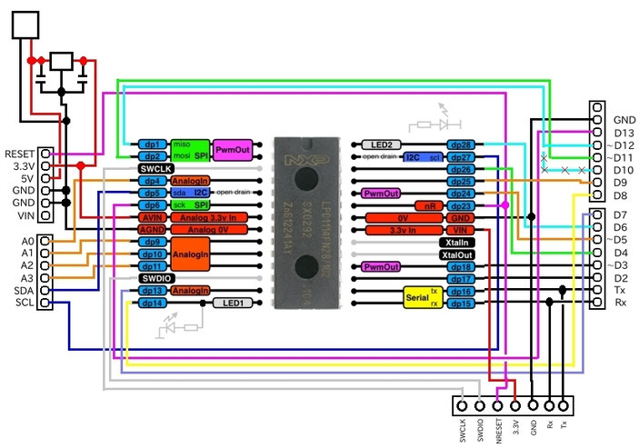
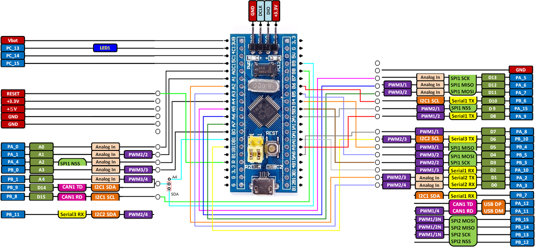
LPC1114FDH28/102はATmega328Pと同じ28Pinといっても、SWCLK,SWDIOはmbedインターフェース専用とするのでPin数が不足しD10 D12が未接続です。
PWMOutも4Pinしかありません。
A4,A5もI2C SDA,SCL用です。(open drainのためI2C以外で使用する場合は注意が必要)
あとスケッチもArduinoとmbedでは違うので、Pin番号だけ同じになるだけです。
同じというか、例 8 → D8になります。
コード自体はmbed用に移植が必要です。
mbedのプラットホームはMCUが違うとPin名も変わってしまいます。
STM32F1、STM32F4のMCUだとArduino IDEを使って開発できるので便利です。
//shield.h
#define D0 dp15
#define D1 dp16
#define D2 dp17
#define D3 dp18
#define D4 dp26
#define D5 dp24
#define D6 dp28
#define D7 dp13
#define D8 dp14
#define D9 dp25
//#define D10 dp1
#define D11 dp2
#define D12 dp1
#define D13 dp6
#define D14 A0
#define D15 A1
#define D16 A2
#define D17 A3
//#define D18 SDA
//#define D19 SCL
#define A0 dp4
#define A1 dp9
#define A2 dp10
#define A3 dp11
#define SDA dp5
#define SCL dp27
#define PWM0 D10
#define PWM1 D11
#define PWM2 D5
#define PWM3 D3
//#define PWM4 ??
//#define PWM5 ??
#define RX D0
#define TX D1
//#define ARD_SDA p9
//#define ARD_SCL p10
#define MOSI D11
#define MISO D10
#define SCK D13
#define SERIAL_TX D1
#define SERIAL_RX D0
//main.cpp
#include "mbed.h"
#include "shield.h"
//DigitalOut myled(LED1); //ok
//DigitalOut myled(dp26); //ok
//DigitalOut myled(xp23); //dp6 ok
//DigitalOut myled(xp40); //dp18 ok
DigitalOut myled(D8); //dp14 ok #include "shield.h"が必要
int main() {
while(1) {
myled = 1;
wait(1.0);
myled = 0;
wait(1.0);
}
}
LPC111x用 mbeduino計画
計画内容
開発環境 : mbed Platforms :mbed LPC1114FN28
Arduinoのシールドがそのまま使用できることを目指す。
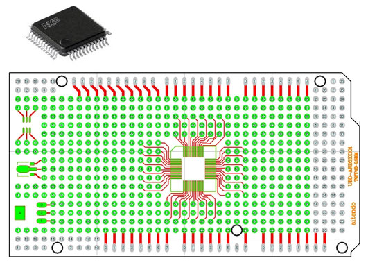
部品表
MCU(LPC111xの48pin以上)
LPC1114FBD48/302 190円+税+送料(aitendo)
LPC1115FBD48/303 416円+送料2000円(Digi-Key-米国発送、5日で届きました)
PCB
プロトタイプシールド基板 [UBD-ARD53X101] 250円+税+送料(aitendo)
(TQFP48-0.5 : MCUはLQFP48-0.5だがいくら見ても基板のパターンは
同じにしか見えない)
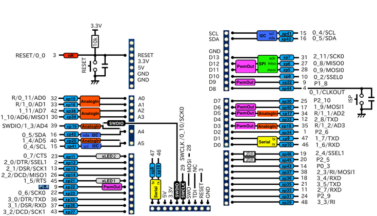
ピン番号変換
Arduino LPC111x - mbeduino LPC111x(48Pin)Pin番号
A5 , SCL , SCL xp41 15
A4 , SDA , SDA xp42 16
13 , SCK D13 , SCK xp7 31
12 , MISO D12 , MISO , PWM xp6 27
11 , MOSI , PWM D11 , MOSI , PWM xp5 28
10 , SS , PWM D10 , SSEL xp8 10
9 , PWM D 9 , PWM xp22 9
8 , CLKO D 8 , CLKOUT xp44 4
7 , D 7 xp33 11
6 , PWM D 6 , PWM xp40 17
5 , PWM D 5 , PWM xp17 34
4 , D 4 xp32 12
3 , PWM D 3 , PWM xp18 35
2 , D 2 xp34 1
1 , TXD D 1 , TXD xp9 47
0 , RXD D 0 , RXD xp10 46
A0 , D14 A0 , D14 xp15 32
A1 , D15 A1 , D15 xp16 33
A2 , D16 A2 , D16 xp38 42
A3 , D17 A3 , D17 xp39 30
A4 , D18 , SDA JPで切り替え A4 , D18 xp19 39 --- SDA xp42 16 --- SWDIO
A5 , D19 , SCL JPで切り替え A5 , D19 xp20 40 --- SCL xp41 15
eBayでのトラブル
よくネットでeBayは安いと書かれていたので、最近はeBayばかりで購入していました。
本当に安い。amazonの50〜70%の金額で購入できる。しかも送料無料。
(全ての商品が送料無料ということではありませんので注意してください。特にアメリカ発送だと商品がいくら安くても送料が2000〜3000円(宅配便の場合)はします。)
今回、初めてトラブルがあったのですが英語が全然できないのでeBayで購入するのも考える時がきたようです。
ネットで検索しても注文した個数が届かない等のトラブルが多いようです。
しかし、1商品を1個で注文した時は今の所問題ないので、複数個注文するのはやめようかな。
全額返金してくれました。届いた1個も返却しなくて良いとのこと。
連絡して1日で処理してくれました。中国の企業でも良い企業もありますね。
話がそれますが1個100円以下の商品も送料無料で、中国から届きますが郵便局は郵便料金を徴収していないのでしょうね。
届いた商品には航空便と書かれているので、多分 エコノミー航空(SAL)便だと思いますが定形の手紙で中国まで90円ですね。
受け取った国の郵便局はほとんど料金をもらえないのかな?
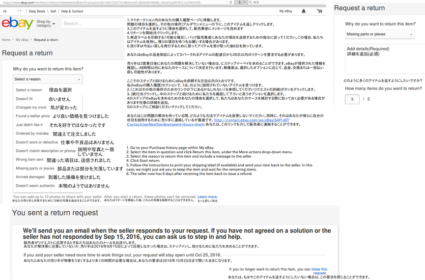
eBayの出品者に対するトラブル対応の控え
英語でメッセージを送らなくてはいけないので大変だ。
Google翻訳さまさまだ。